Pumps, compressors, engines, conveyors, machines, and other manufacturing equipment use oscilloscopes to transform electrical power to mechanical power. The voltage signals that power these electromechanical devices are an essential yet unseen force. So, how can you see and catch the invisible force?
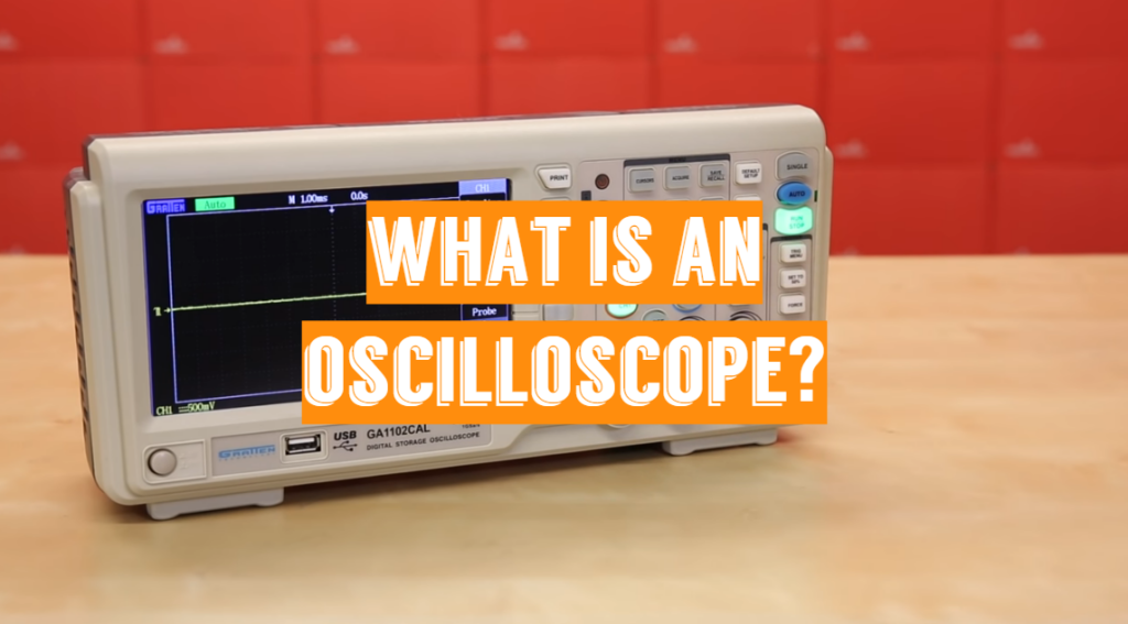
An oscilloscope (also known as an o-scope or just scope) is a graphical display system that displays an electrical signal as a graph or image. The graph depicts how signals shift over time in most applications: the vertical (Y) axis represents voltage, and the horizontal (X) axis represents time. The Z-axis refers to the display’s brightness or intensity. The Z-axis of DPO oscilloscopes may be defined by the display’s color grading.
Who uses oscilloscopes?
Everybody from scientists to maintenance technicians using an o-scope. An automotive technician uses an automotive oscilloscope to compare analog information from sensors with serial data from the car’s engine control module and any range of integrated systems that power today’s wired and autonomous automobiles.
A medical doctor also uses an o-scope to test brain waves.
Engineers to measure power use and usage of anything from microchips to municipal power grids select these devices.
The options are limitless when it comes to the uses of oscilloscopes.
Major types of oscilloscopes:
Analog and digital o-scopes are the two major types of this useful device.
1) Analog
An electron beam is used in analog o-scopes to explicitly map the input voltage to a monitor. Microcontrollers are used in digital o-scopes to sample the input signal using an analog-to-digital converter and map the reading to the monitor. Analog o-scopes are typically older, have limited bandwidth, and fewer capabilities, but they can have a quicker response time (and look better).
2) Digital
In comparison to an analog o-scope, a digital oscilloscope converts calculated voltage into digital data using an analog-to-digital converter (ADC). It obtains the waveform as a sequence of samples and stores them until it has a sufficient number of samples to characterize the waveform. The waveform is then reassembled and shown on the projector by the digital o-scope.
The vertical mechanism, horizontal system, triggers, and monitor system are 4 mechanisms that make up any simple oscilloscope. All o-scopes use these systems to have the most detail about the signal and to enable the consumer to assess the signal’s integrity, predictability, and reliability for a variety of applications.
Anatomy of a Digital Oscilloscope
1) Display
An o-scope is useless unless it can show the data you’re attempting to analyze, so the display is one of the scope’s most valuable features.
Horizontal and vertical lines named divisions should be crossed through any oscilloscope display. The horizontal and vertical structures change the size of certain divisions. The horizontal method is calculated in “seconds per division”. The vertical system is measured in “volts per division”. Contemporary o-scopes usually have 10-14 horizontal (seconds) divisions and 8-10 vertical (voltage) divisions.
Older scopes (particularly those of the analog variety) typically have a plain, monochrome display, though the wave amplitude can differ. Modern scopes include multicolor LCDs, which are extremely useful for displaying many waveforms at once.
Often scope screens have a series of 5 buttons next to them, either below or to the side of the display. These buttons may be used to browse menus and change the scope’s settings.
2) Vertical system
The vertical portion of the scope regulates the voltage level/scale on the monitor. This segment usually has two knobs that enable you to control the vertical location and volts/div separately.
You will adjust the vertical scale on the panel using the more important volts per division knob. The scale would be decreased if you turn the knob clockwise, and increased if you turn it counter-clockwise. You’re more “zoomed in” to the waveform if the size is smaller (fewer volts per division on the screen).
The vertical deviation of the waveform on the panel is regulated by the direction knob. The wave would travel down the monitor if you turn the knob clockwise, and up the display, if you turn it counter-clockwise. The location knob may be used to move sections of a waveform of the display.
3) Horizontal system
The horizontal portion of the scope regulates the time scale. The horizontal system, like the vertical system, has two knobs: direction and seconds/div.
To raise or decrease the horizontal size, turn the seconds per division (s/div) knob. The number of seconds each division covers decreases when you turn the s/div knob clockwise, allowing you to “zoom in” on the time scale. Rotate the time axis counterclockwise to display a prolonged period of time on the computer.
The orientation knob adjusts the horizontal offset by moving your waveform to the left or right of the display.
4) Trigger section
The oscilloscope is stabilized and focused in the trigger section. The sensor instructs the spectrum on which aspects of the signal to “trigger” and measure. The trigger may be changed to hold the output steady and unflinching if the waveform is periodic.
A scope’s trigger section normally consists of a level knob and a series of buttons for selecting the trigger’s source and form. To adjust a trigger to a certain voltage stage, rotate the level knob.
The remainder of the trigger mechanism is made up of a set of buttons and computer menus. They are primarily used to choose the trigger mode and source. There are many different kinds of triggers, one of which affects how the trigger is activated:
- Edge trigger. It is the simplest kind of trigger. When the signal voltage reaches a certain threshold, it will activate the oscilloscope to begin testing. An edge trigger may catch a growing or dropping edge (or both);
- Pulse trigger. It instructs the scope to focus on a certain voltage “pulse.” You can control the pulse’s length and direction;
- Slope trigger. A slope trigger may be used to activate the scope as it encounters a positive/negative slope for a set period of time;
In certain cases, you will even use a triggering mode that shows of how deeply the scope is towards the signal. Even if the scope does not trigger, it will attempt to draw the waveform in automatic trigger mode. In normal mode, your wave will only be drawn if the defined trigger is detected. A single mode, on the other hand, searches for the defined trigger to draw the wave and then stop it.
5) Probes
Probes stand for single-input devices that connect your circuit to your scope. They have a sharp tip that probes through a circuit spot. To make latching onto a circuit simpler, the tip may be fitted with loops, tweezers, or clips. A ground clip is included for each probe and should be securely attached to a standard ground point on the circuit under test.
Although probes seem to be basic devices that lock onto the circuit and send a signal to the scope, there’s a lot more to probe architecture and selection than meets the eye.
A probe should ideally be undetectable – it should have little impact on the signal under test. Long cables, unfortunately, all have inherent capacitance, inductance and resistance, so they’ll impact scope readings no matter what (especially at high frequencies).
The most popular form of the probe is the passive probe, which comes standard with most scopes. The majority of “standard” passive probes have been attenuated.
Attenuated probes are useful for improving precision at high frequencies, however, they reduce the signal’s amplitude. If you’re trying to test a really low-voltage signal, a 1X probe may be essential. While several scopes will automatically detect this, you can need to pick a setting on the scope to inform it you’re using an attenuated probe.
Basic Oscilloscope Functions
1) Sampling
The method of transforming a component of an input signal into a set of distinct electrical values for storage, processing, and the display is known as sampling. The amplitude of the input signal at the moment the signal is sampled is proportional to the magnitude of each sampled value.
On the oscilloscope monitor, the input waveform emerges as a sequence of dots. If the dots are closely scattered and complicated to understand as a waveform, interpolation that connects the dots with lines or vectors may be used to align them.
Interpolation and sampling: the circles represent sampling, while the black line represents interpolation.
2) Triggering
A repeated waveform may be stabilized and shown using trigger controls. The most popular form of triggering is edge triggering. The trigger level and slope controls define the simple trigger point concept in this mode. The slope control decides when the trigger point occurs on a signal’s rising or dropping edge, while the level control determines where the trigger point occurs on the edge.
Pulse-width triggering can be expected when dealing with complicated signals such as a sequence of pulses. Both the trigger-level setting and the next dropping edge of the signal must occur within a given timeframe while using this technique. The o-scope activates when these two requirements are reached.
Single-shot triggering is another process, in which the oscilloscope displays a trace only when the input signal reaches the trigger conditions. The o-scope acquires and upgrades the monitor until the trigger requirements are satisfied, then freezes the display to keep the trace.
Major specifications of an o-scope:
- Bandwidth. O-scopes are more widely used to calculate frequency-defined waveforms. However, no reach is perfect: they both have a limit on how quickly they can detect a signal shift. The spectrum of frequencies that scope may accurately quantify is described by its bandwidth;
- Channels. Many scopes will interpret several signals at once and view them all on the computer at the same time. A scope reads each signal and sends it to a different channel. Scopes with 2 or 4 channels are very normal;
- Sampling rate. This feature is exclusive to digital scopes, and it determines how many times a signal is read per second. If multiple channels are used in scopes of more than 1 channel, this value can decrease;
- Rise time. The fastest growing pulse that scope can calculate is described by its raise period. The bandwidth and the rise period of a scope are inextricably linked. Rise Time = 0.35 / Bandwidth may be used to quantify it;
- Maximum input voltage. When it comes to high voltage, any piece of circuitry has its limits. Both scopes should have a maximum input voltage rating. There’s a fair risk the target would be damaged if the signal crosses that voltage;
- Resolution. A scope’s resolution indicates how accurately it will calculate the input voltage. If the vertical scale is changed, this value will shift;
- Vertical sensitivity. The maximum and minimum values of your vertical voltage scale are described by this value. This number is expressed in volts per division;
- Time base. On the horizontal, time axis, the term “time basis” typically refers to the continuum of sensitivities. This value is stated per div in seconds;
- Input impedance. Even a minor impedance (capacitance, resistance, or inductance) applied to a circuit may influence the signal when signal frequencies are very large. The input impedance adds a certain amount of impedance to the circuit it is interpreting. When testing very high-frequency signals, the effect of input impedance is more noticeable, and the probe you use will need to adjust for it;
Final thoughts
Oscilloscopes are a form of electronic research equipment that is commonly used. They offer a high degree of visibility into a circuit’s activity and are essential for identifying and addressing several problems, whether in electronics manufacturing tests, RF design, general electronic circuit design, service, repair, or even field service.