
A resistor is a two-terminal passive electrical part that acts as a circuit element by implementing electrical resistance.
Resistors are used in electrical circuits for a variety of purposes, including reducing current movement, adjusting signal speeds, dividing voltages, biasing active components, and terminating transmission lines.
A resistor is a component that regulates the flow of current in a circuit. Resistors are constructed of materials that make it impossible for charges to pass through a circuit, such as copper or carbon.
A carbon resistor is the most popular kind of resistor. It is a general-purpose resistor that is better designed for lower-powered circuits. The wire-wound resistor and film resistor are two more typical resistor forms.
Why do you need to use resistors?
Most electoral circuits need resistors, and they can be used for a wide range of applications:
- Prevent the voltage spikes. Additionally, resistors shield components from voltage surges. If there is no resistor to regulate the flow of the electrical current, components that are vulnerable to a strong electrical current, such as LED lamps, will be affected. Fuse and circuit breakers may be used to shield the electrical circuit from voltage surges as well;
- Check the required voltage. Resistors shield components from voltage surges and guarantee that they obtain the correct voltage by causing a voltage decrease. A particular voltage is needed for each part of an electrical circuit, such as a light or a switch.
- A resistor can produce a voltage decrease if a device in your circuit receives less voltage than the majority of the circuit. This ensures that the component does not absorb so much voltage. By delaying, or resisting, the particles as they continue to flow through the resistor, the resistor can trigger a voltage decrease. A component can be disabled or unable to perform properly if it absorbs too much voltage. When switching from incandescent to LED turn signals, an LED load resistor is provided for each light to ensure proper operation. The LED load resistor causes a voltage drop, which allows the LED turn signals to blink at the correct rate. The LED switch indicator would flash too quickly if the LED resistor was not mounted, and the high voltage would inevitably kill it;
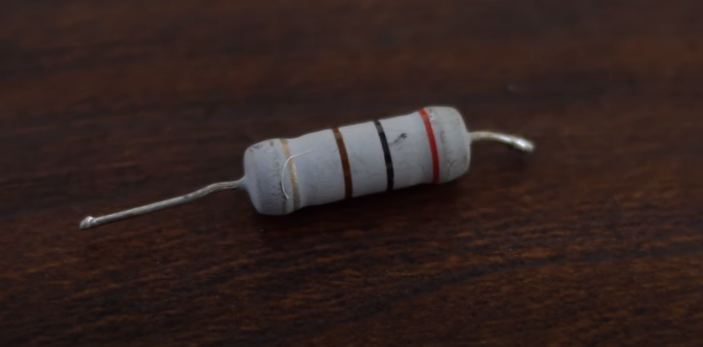
Resistors come in a variety of forms and sizes. Resistor color code is a pattern of colored bands used to denote resistance value, tolerance, and often also the temperature coefficient on almost all leaded resistors with a power level of up to one watt.
A resistor’s body may have anywhere from three to six colored bands, with 4 bands being the most typical. The first bands are often digits in the resistance value. And there’s a multiplier band to indicate if you’re pushing the decimal left or right. The temperature coefficient and tolerance are described by the last two bands.
Resistors come in a variety of shapes and sizes, and they may be applied in both electrical and computer circuits to regulate current flow or generate voltage drops in a variety of ways. However, the real resistor must have some kind of “resistive” or “resistance” value in order to accomplish this.
Resistors come with a variety of resistance values ranging from fractions of an Ohm (Ω) to millions of Ohms.
Obviously, using resistors of any conceivable value, such as 1Ω, 2Ω, 3Ω, 4Ω, and so on, would be impossible since practically tens of thousands, if not tens of millions, of different resistors, would be needed to cover all possible values. Alternatively, resistors are made of what is known as “preferred values” with the resistance value written in colored ink on the device’s body.
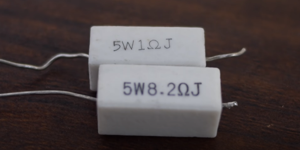
The resistor color code’s system is generally not used on larger power resistors since the resistance, tolerance, and even the power (wattage) value are written on the actual body of the resistor rather than utilizing the resistor color code system. Since it’s all too simple to “misread” the location of a decimal point or comma, particularly if the part is discolored or dirty. The resistance ideals of the human resistance were written and printed in a more user-friendly manner.
Why do you need to learn resistor color codes?
So, what’s the big deal with color-coding of resistors? Isn’t it possible to stamp or paint the resistance value on the body of the through-hole resistor? Yes, but the figures will be tiny and impossible to decipher. You can’t interpret the meaning of a resistor with the labeled side down until you pull it out of the circuit. Furthermore, the marks can quickly wear off or smear with time.
Resistor color-coding employs colored bands to quickly define the resistive value and percentage tolerance of a resistor.
[tds_info]If you grasp the context and math behind each band used to denote resistance, tolerance, and often even the temperature coefficient, interpreting color codes is easy.[/tds_info]Resistor Color codes are sometimes used to denote resistor values. Color bands are used to identify almost all leaded resistors with a power level of less than one watt. The IEC 60062 universal standard specifies the coding. The labeling codes for resistors and capacitors are defined in this standard. It also has numerical codes, such as those used by SMD resistors.
Several bands have the color code. They define the resistance value, tolerance, and, in certain cases, the stability or failure rate when used together. The number of bands will range anywhere from three to six. Two bands are used to represent the resistance value, with one band serving as a multiplier. Resistance values are structured and referred to as desired values.
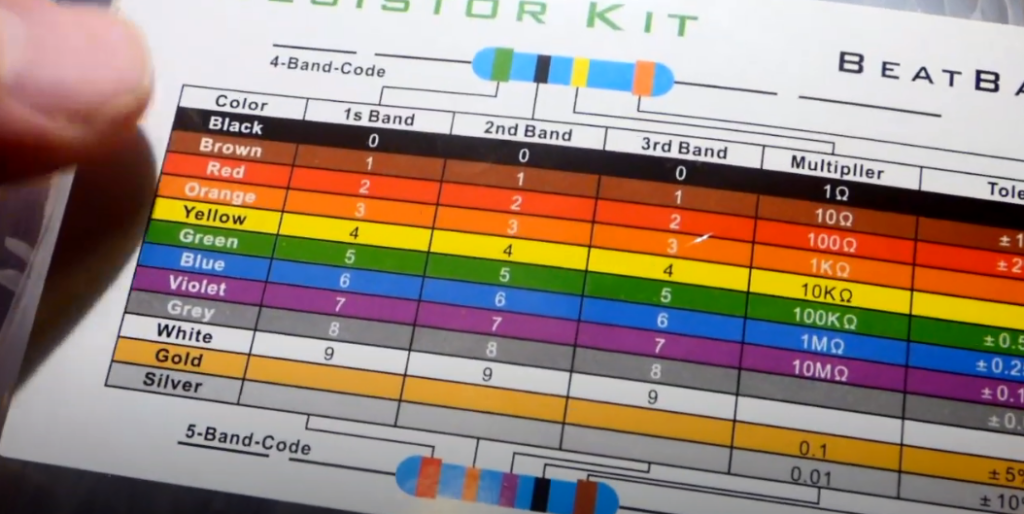
The chart to determine the tolerance and resistance with resistor color codes:
| Mnemonic phrase |
Color | Significant figures | Multiply | Tolerance (%) | Temp. coeff. (ppm/K) | Fail rate | ||
| Bad | Black | 0 | 0 | 0 | X 1 | 250 (U) | ||
| Beer | Brown | 1 | 1 | 1 | X 10 | 1 (F) | 100 (S) | 1 |
| Rots | Red | 2 | 2 | 2 | X 100 | 2 (G) | 50 (R) | 0.1 |
| Our | Orange | 3 | 3 | 3 | X 1K | 15 (P) | 0.01 | |
| Young | Yellow | 4 | 4 | 4 | X 10K | 25 (Q) | 0.001 | |
| Guts | Green | 5 | 5 | 5 | X 100K | 0.5 (D) | 20 (Z) | |
| But | Blue | 6 | 6 | 6 | X 1M | 0.25 (C) | 10 (Z) | |
| Vodka | Violet | 7 | 7 | 7 | X 10M | 0.1 (B) | 5 (M) | |
| Goes | Grey | 8 | 8 | 8 | X 100M | 0.05 (A) | 1 (K) | |
| Well | White | 9 | 9 | 9 | X 1G | |||
| Get | Gold | 3rd digit only for 5 and 6 bands | X 0.1 | 5 (J) | ||||
| Some | Silver | X 0.01 | 10 (K) | |||||
| Now! | None | 20 (M) | ||||||
Understanding standard codes and values
Colors are used to describe the importance and role of various elements and wires.
Resistor Color Coding employs colored bands to easily define a resistor’s resistive value and tolerance percentage, with the resistor’s physical size representing its wattage rating.
If a resistor’s body is wide enough to read the text, such as massive power resistors, the resistance, tolerance, and wattage rating are usually written as numbers or letters on the resistor’s body.
However, since the print on a smaller resistor is too thin to decipher, the specs must be displayed in a different manner.
Just 5-band resistors have tolerance codes in the colors brown, red, green, blue, and violet. A colored tolerance band appears on any 5-band resistor.
Only the 4-band code (3 colored bands + a blank band) uses the blank (20 percent) band.
Related Review: Circuit Testers
Useful tips
Sometimes the reading route isn’t obvious for the user who has never used resistors with colored bands. The enhanced space between bands 3 and 4 will often reveal the reading path. In addition, the first band is always the nearest to a lead. The last band is often a gold or silver band (the tolerance).
It’s a smart idea to double-check the manufacturer’s manual to make sure the coding scheme is right. It’s much safer to use a multimeter to check the resistance. In certain situations, this might be the only way to determine the resistance, such as where the color bands have been burned off:
1) 4-band code
The most popular code is a four-band system. There are two resistance bands, one amplifier, and one tolerance band on these resistors. These bands are gray, blue, red, and gold. Applying the color code table, one can see that green represents 5 and blue represents 6. As a result, the meaning is 56100 = 5600. The golden band indicates that the resistor has a 5% tolerance. As a result, the resistance value falls between 5320 and 5880. The effect is a three-band resistor if the tolerance band is left blank. This suggests that the resistance is unchanged, but the tolerance is increased by 20%.
2) 5-band code
A third relevant digit is shown by an extra band on high-precision resistors. As a result, the first three bands denote major digits, the fourth band denotes the multiply component, and the fifth band denotes tolerance. There are few exceptions. The extra band, for example, can mean a failure rate (military specification) or a temperature coefficient (outdated models or special resistors).
3) 6-band code
High-precision devices with an extra band to determine the temperature coefficient (ppm/K) are commonly used in resistors with six bands. Brown (100 ppm/K) is the most popular color for the sixth band. This implies that the resistance value will shift by 0.1 percent with every 50F change in temperature. Other colors are used in particular applications where the coefficient is important.
Exceptions for this color system:
- Reliability band. An extra band is often added to military-specified resistors to signify durability. This is expressed as a percentage of failures per 1000 hours of operation. In consumer electronics, this is an unusual occurrence. The durability band is most often seen on four-band resistors;
- Single black band or zero-ohm resistor. It has a single black band. It is primarily a wire connection with the sole purpose of linking traces on a PCB. Applying the resistor kit has the benefit of allowing components to be placed on a circuit board using the same automatic machines;
- The 5th band resistor with the 4th band of gold or silver. Such devices with a gold or silver fourth band are the exception and are found on advanced and older resistors. The significant digits are described by the first two bands, the multiplying factor by the third, the tolerance by the fourth, and the temperature coefficient (ppm/K) by the fifth;
- Replaced colors. The gold and silver colors are often substituted for yellow and gray in high voltage resistors. This is to keep metal fragments out of the coating;
Mnemonic catchphrases to remember color codes
It is sometimes simpler to recall the color code of the resistor by using brief, quickly remembered phrases in the form of expressions, rhymes, and phrases, called acrostic, which include a different term in the sentence to denote each of the Ten + Two colors.
The mnemonic phrases compare the first letter of each term to every color that represents the color code, and several various mnemonic phrases may be used. However, these proverbs are often crude, but they are nevertheless good at remembering resistor colors. Here are a couple of the “cleaner” models, but there are several more:
- Bad Boys Ring Our Young Girls But Vicky Goes Without;
- Bad Booze Rots Our Young Guts But Vodka Goes Well (in) Silver Goblets (this phrase includes gold and silver band colors);
FAQ
Which end of the resistor to start reading the color code?
- Certain color bands are clustered closer together or at one end with several resistors. On your hand, hold the device with these clustered bands. When reading resistors, often read them from left to right;
- Resistors won’t begin with a left-hand metallic band. A device with a gold or silver band on one end is referred to as a 5 percent or 10% tolerance resistor. Place the resistor on the right side of the band, and read the resistor from left to right once more;
- Standard device values vary from 0.1 to 10 megaohms. With this experience, remember that the third color on a four-band resistor will always be blue (106) or less, and the fourth color on a five-band resistor will always be green (105) or less;
What about a zero-ohm resistor?
Zero-ohm resistors (you may recognize them by single black band) are essentially wire links applied to attach traces on a printed circuit board. Since they are packaged similarly to resistors, they may be placed on the board using the same automatic machinery as is used to position resistors. This configuration eliminates the need for a jumper wire installation.
What is a reliability band?
On four-band resistors, an extra band is often used to signify durability or the failure rate (percent) per 1000 hours of operation. In consumer electronics, this is seldom used.
How to calculate the resistance value with color codes?
To find the resistance frequency, group the values of the important digits bands — that is, the first 2-3 bands from the left, based on the amount number of bands. Then multiply the value by the multiplier to obtain the resistor’s resistance value.
Take a 4-band resistor, for example, with such colors: Violet Green Yellow Gold
The first colors (violet and green) would signify the important digits, which are 75 since it is a four-band resistor.
Then multiply the result by the multiplier shown by the third band (yellow), which is x104 = 10000.
75 x 10000 = 750000 = 750k is the result of the multiplication.
The 4th band (gold) will show the tolerance, which in this case is 5%.
Multiply the resistance value by the tolerance percentage to get the minimum and maximum resistance values:
Minimum = 712.5kΩ
Maximum = 787.5kΩ
Related Video: Resistor Color Code Chart Tutorial Review
Final thoughts
The color code for resistors can seem complicated and awkward at first, but most hobbyists and technicians are astonished at how easily they can memorize the color chart without using mnemonics or other stupid shortcuts. The color code is rather simple, and after a short duration of familiarization, identifying resistor values immediately would become second nature.